Semantic search
Jump to navigation
Jump to search
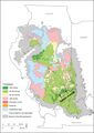 '''Figure 1''' Map of the Illinois Basin showing the extent of Pennsylvanian rocks, thickness of the Springfield Coal, and channels interrupting the coal. From Finley et al. (2005)'"`UNIQ--ref-00000001-QINU`"'. Straight lines separating polygons are artifacts of mapping protocol in original.
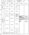 '''Figure 2''' Correlation chart showing the positions of key units within the Pennsylvanian Subsystem. Global and provincial stage boundaries and ages in millions of years (Ma) are after Gradstein et al. (2012)'"`UNIQ--ref-00000001-QINU`"'.
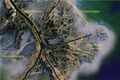 '''Figure 3''' Satellite image of the mouth of the Mississippi River showing natural levees and crevasse splays. Fron Earthstar Geographic SIO, © 2020.
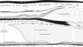 '''Figure 4''' Diagram showing units between the Houchin Creek and Herrin Coals, including members newly named in this report.
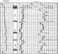 '''Figure 5a''' Wireline log illustrating the typical response of key units. (a) Electric log of Carter Oil No. 1 Beers well in sec. 28, T8S, R4E, Williamson County, Illinois (county no. 2107). B, Brereton Limestone; H, Herrin Coal; Sp, Springfield Coal; Han, Hanover Limestone; HC, Houchin Creek Coal; SV, Survant Coal; MQ, Mecca Quarry Shale; C, Colchester Coal. (b) Gamma-ray–resistivity log of Peabody Natural Gas No. 2 Short, in sec. 14, T7S, R7E, Hamilton County (county no. 25375).
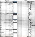 '''Figure 5b''' Wireline log illustrating the typical response of key units. (a) Electric log of Carter Oil No. 1 Beers well in sec. 28, T8S, R4E, Williamson County, Illinois (county no. 2107). B, Brereton Limestone; H, Herrin Coal; Sp, Springfield Coal; Han, Hanover Limestone; HC, Houchin Creek Coal; SV, Survant Coal; MQ, Mecca Quarry Shale; C, Colchester Coal. (b) Gamma-ray–resistivity log of Peabody Natural Gas No. 2 Short, in sec. 14, T7S, R7E, Hamilton County (county no. 25375).
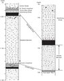 '''Figure 6''' Graphic logs from cores serving as type sections of the newly named members: (a) Energy Plus borehole no. ME-13 in sec. 31, T4S, R6E, type section of the Delafield Member. (b) Kerr-McGee borehole no. 7629-16 in sec. 29, T7S, R6E, Saline County, type section of the Galatia Member.
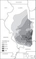 '''Figure 7''' Isopach map of the Delafield Member. After Wanless et al. (1970)'"`UNIQ--ref-00000001-QINU`"'. Thicknesses are in feet.
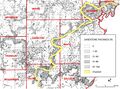 '''Figure 8''' Map from Potter (1962)'"`UNIQ--ref-00000006-QINU`"', showing the thickness (in feet) of sandstone between the Houchin Creek and Springfield Coals, with the Galatia channel (from Hopkins 1968'"`UNIQ--ref-00000007-QINU`"') superimposed.
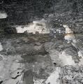 '''Figure 9''' Photograph showing underclay of the Springfield Coal at American Coal’s Galatia Mine, Saline County, Illinois. Field of view approximately 5 ft (1.5 m) square.
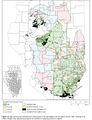 '''Figure 10''' Map showing the thickness and mined areas of the Springfield Coal throughout Illinois. After Treworgy et al. (1999)'"`UNIQ--ref-00000001-QINU`"'. Straight lines separating polygons are artifacts of mapping protocol in original.
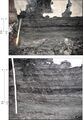 '''Figure 11''' Photographs showing thinly interlaminated shale and dull to bright coal along margins of the Galatia channel at the Prosperity Mine in Gibson County, Indiana. The lower frame is a closer view of the upper. The ruler is graduated in 0.1-ft intervals.
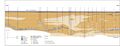 '''Figure 12''' Cross section of Galatia channel in American Coal’s Galatia Mine in Saline County, Illinois, based on core drilling and observations in mine.
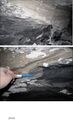 '''Figure 13''' Photographs showing the ragged, erosive contact between the light-colored siltstone of the Dykersburg Member and the underlying coaly shale of the Galatia Member in the channel crossing at the Galatia Mine, Saline County, Illinois. (a) View of the east wall of the entry. Coaly shale of the Galatia Member grades laterally northward (left, out of view) to shaly Springfield Coal. The pick is approximately 2 ft (60 cm) long. (b) Close-up view on the west wall of the entry. The heart of the Galatia channel is south (left) of view. Notice how erosion undercut the clay below layers of tough, fibrous peat.
 '''Figure 14''' Map showing the thickness of the Dykersburg Member in the vicinity of Galatia channel in southeastern Illinois. From Treworgy et al. (1999)'"`UNIQ--ref-00000001-QINU`"'.
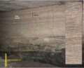 '''Figure 15''' Photograph showing rhythmic lamination in sandy facies of the Dykersburg Member in American Coal’s Millennium Mine, Saline County, Illinois. Enlarged view at right. Reprinted from Palaeogeography, Palaeoclimatology, Palaeoecology, v. 487, p. 74, W.A. DiMichele, S.D. Elrick, and W.J. Nelson, Vegetational zonation in a swamp forest, Middle Pennsylvanian, Illinois Basin, U.S.A., indicates niche differentiation in a wetland plant community. Copyright 2017, with permission from Elsevier.
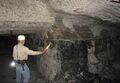 '''Figure 16''' Photograph showing rhythmic lamination in sandy facies of the Dykersburg Member in the Millennium Mine, with lamination offlapping the top of the coal. Sediment thus was deposited in a wedge, prograding from left to right.
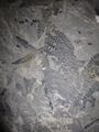 '''Figure 17''' Photographs showing large, well-preserved fronds of fossil plant foliage (Laevenopteris?) in the Dykersburg Member at Millennium Mine, Saline County, Illinois.
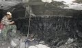 '''Figure 18''' Photograph of an upright tree stump, rooted at the top of the coal and encased in mudstone of the Dykersburg Member, at American Coal’s Galatia Mine in Saline County, Illinois.
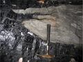 '''Figure 19''' Photograph of “rolls” at the top of the Springfield Coal, filled with Dykersburg sediments, at American Coal’s Millennium Mine in Saline County, Illinois. Ragged splaying of coal layers at the margins of rolls evokes fibrous peat layers ripped out by strong currents.
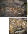 '''Figure 20''' Photographs showing the Springfield Coal “split” by massive siltstone in the Millennium Mine. The lower view is a close-up of the upper view. Notice the ragged splaying of coal layers into the siltstone from both above and below, with one coal stringer crossing diagonally from the lower to the upper coal “bench.” Combined with the absence of roots beneath the upper bench, such geometry implies that the upper part of the peat deposit was rafted. Enlarged view at right. Brown and yellow stains resulted from iron-rich water seeping through the coal.
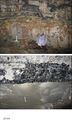 '''Figure 21''' Photographs of siltstone “splits” in the Springfield Coal. (a) Upper “bench” of coal splitting into multiple layers, with ragged splaying of lower coal layers at the Millennium Mine. (b) Contact between the upper coal bench and a massive siltstone split in American Coal’s Millennium Mine, approximately 0.6 mi (1 km) west of the main Galatia channel. Notice the complete absence of root traces in the siltstone.
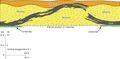 '''Figure 22''' Profile view of the disturbance in Figure 21a in the Millennium Mine, Saline County, Illinois.
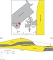 '''Figure 23''' Profile view of the disturbance Figure 21b in the Millennium Mine. The map shows the relationship to the Galatia channel.
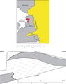 '''Figure 24''' Map and cross section of the disturbance in the Sahara No. 20 Mine, Saline County, Illinois.
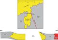 '''Figure 25''' Map and cross section of the disturbance in the Dering Coal Company No. 2 Mine, Saline County, Illinois. Redrafted from field sketches by Rolf Roley and G.H. Cady in the ISGS archives.
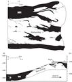 '''Figure 26''' Drawings from Meier and Harper (1981)'"`UNIQ--ref-00000001-QINU`"' illustrating a major disruption of the Springfield Coal in AMAX Coal’s Wabash Mine in Wabash County, Illinois.
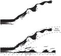 '''Figure 27''' (Top) Image of the major disturbance in the Wabash Mine. From Meier and Harper (1981). (Bottom) The same drawing with interpretation added, depicting the peat deposit torn asunder, with the upper part floated away from the lower. The seam height at the left side of the diagram is approximately 9 ft (2.7 m).
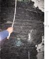 '''Figure 28''' Photograph of interlaminated carbonaceous shale and bright to dull coal close to the margin of the Sullivan channel in the Oaktown Mine in Knox County, Indiana.
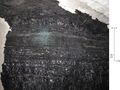 '''Figure 29''' Photograph of interlaminated carbonaceous shale and bright to dull coal close to the margin of the Sullivan channel in the Oaktown Mine in Knox County, Indiana.
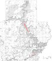 '''Figure 30''' Map from Potter (1962)'"`UNIQ--ref-00000001-QINU`"' showing the Effingham channel as described in this report.
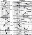 '''Figure 31''' Gamma-ray–neutron log from the Berry Petroleum No. 11-14 Pitcher well in Jasper County, Illinois, indicating coal in the upper part of the Effingham channel fill.
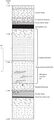 '''Figure 32''' Graphic log of core from Richland County, Illinois, showing filling of the Effingham channel. The core shows two upward-fining sequences, the lower having tidal rhythmites in the upper part. The borehole is ISGS No. 1 Elysium (Hazel Farm) in sec. 27, T4N, R9E (county no. 25922).
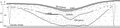 '''Figure 33''' Interpretive cross section of the Effingham channel in Richland County, Illinois, showing two stages of infilling, with local coal at the top of the lower stage.
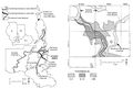 '''Figure 34''' Maps of the Leslie Cemetery channel. (a) Regional map showing the relationship to other channels. (b) Map of the northern part of the Leslie Cemetery channel, with the thickness of the Folsomville Member. From Eggert (1984), The Leslie Cemetery and Francisco distributary fluvial channels in the Petersburg Formation (Pennsylvanian) of Gibson County, Indiana, U.S.A., in R.A. Rahmani and R.M. Flores, eds., Sedimentology of coal and coal-bearing sequences: International Association of Sedimentologists, Special Publication 7 p. 311, 313. Copyright © 1984 The International Association of Sedimentologists.
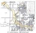 '''Figure 35''' Map of the Leslie Cemetery channel prepared for this study, using information from boreholes and mines. Lines of section for Figure 36 and Plate 6 are shown.
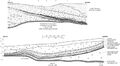 '''Figure 36''' Generalized sketches illustrating opposite margins of the Leslie Cemetery channel, as exposed in surface mines in the eastern half of 9S, 4W, Warrick County, Indiana. The upper image is from Peabody’s Lynnville Mine in July 1983, representing the northern half of the channel. The lower image is from Peabody’s Eby Pit in June 1982, representing the southern half of the channel.
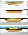 '''Figure 37''' Interpretive diagram showing sequential development of the Leslie Cemetery channel. (a) The Francisco channel is eroded and filled with sediment, largely sand. (b) Springfield peat accumulates in swale left by the abandoned channel. (c) Flowing water reoccupies the channel during the later stages of peat accumulation. Peat encroaches from the margins as the channel migrates laterally. (d) A marine incursion drowns the region and deposits black shale and limestone. Channel filling inverts the topography because of differential compaction.
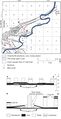 '''Figure 38''' Map and cross section of the Terre Haute channel. From Friedman (1960)'"`UNIQ--ref-00000001-QINU`"'. Courtesy of the Indiana Geological and Water Survey. Lines of cross section are shown on the map.
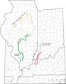 '''Figure 39''' Map of the Illinois Basin showing channels and gray shale wedges affecting the Murphysboro, Colchester, Herrin, Baker, and Danville Coals.
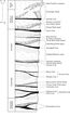 '''Figure 40''' Stratigraphic column showing the units mentioned in the section on channels affecting coal seams other than the Springfield.
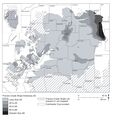 '''Figure 41''' Isopach map of the Francis Creek Shale.
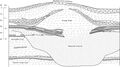 '''Figure 42''' Interpretive cross section of the Herrin Coal, Walshville channel, and Energy Shale.
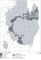 '''Figure 43''' Map showing the Walshville channel and sulfur content of the Herrin Coal. After Treworgy et al. (2000)'"`UNIQ--ref-00000001-QINU`"'. The four named areas of low-sulfur coal are all associated with thick Energy Shale adjacent to the channel.
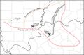 '''Figure 44''' Map showing the Winslow–Henderson channel.
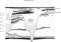 '''Figure 45''' Interpretive cross section of the Winslow-Henderson channel. BR, Brereton Limestone; HR, Herrin Coal; BH/BT, Briar Hill/Bucktown Coal; SD/AC, St. David/Alum Cave Limestone; TM, Turner Mine Shale.
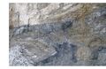 '''Figure 46''' Disruption of the Danville Coal, with the seam “split” by a thick wedge of mudstone. Note the ragged splaying of coal into mudstone, with a thin coal stringer crossing diagonally from the lower to upper “bench.” The site is the box cut at a portal of the Prosperity Mine in Gibson County, Indiana.
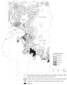 '''Figure 47''' Map showing the thickness of the Murphysboro Coal near the Oraville channel in Jackson and Perry Counties, southwestern Illinois. From Jacobson (1983)'"`UNIQ--ref-00000001-QINU`"'
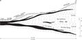 '''Figure 48''' Interpretive cross section of the Oraville channel.
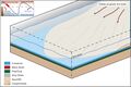 '''Figure 49''' Stage 1: Deposition of the Delafield Member as a series of coalescing deltas during the onset of a glacial stage as the sea level began to fall. The product is a thick succession of clastic rocks that coarsen upward.


